| Beef: | °c Idle | °c Load | |
|---|---|---|---|
| CPU | Intel Core2Duo E6600 2.4ghz @ 3.2ghz | 33 | 56 |
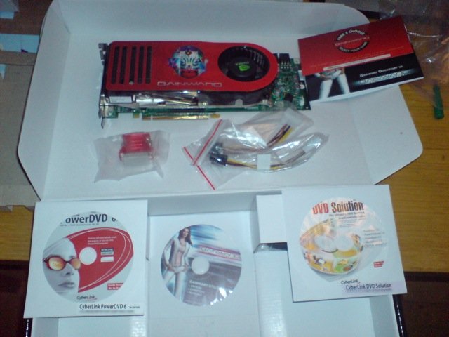
| GPU | Nvidia 8800 GTX | 68 | 89 |
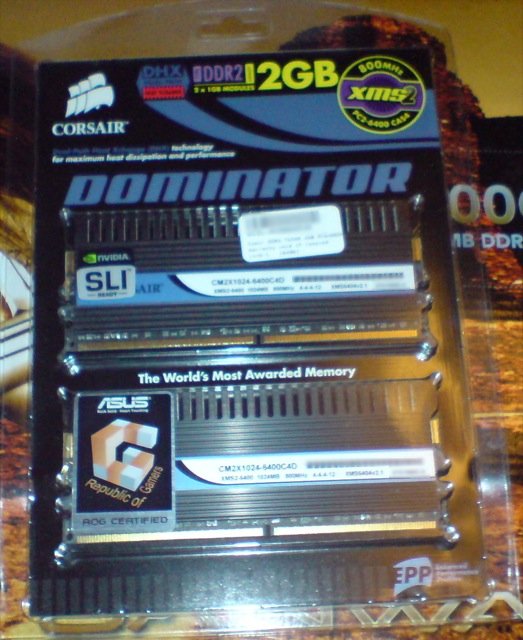
| RAM | 4gb Corsair XMS2 PC6400 | ||
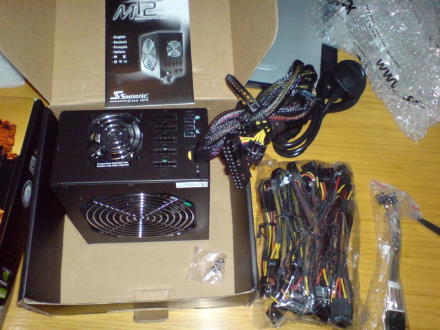
| PSU | Seasonic M-12 500w | ||
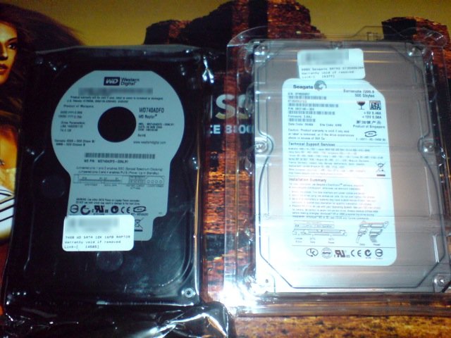
| SATA1 | Western Digital 10k 74gb Raptor | 37 | 40 |
| SATA2 | Seagate 7200.10 500gb Barracuda | 40 | 40 |
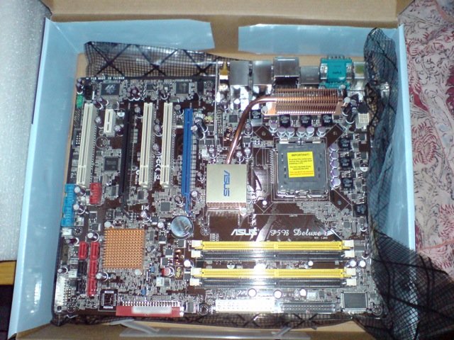
| MB | Asus P5B Deluxe Wifi/AP | ||
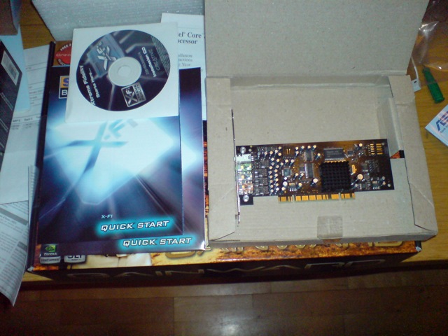
| Audio | Creative X-Fi Gamer | ||
| Case | Antec P180B | 41 | 47 |
| Cake: | |||
| Fans: | 4x Scythe S-Flex 21D, 1x Scythe S-Flex 21E on Acoustimax fan dampers. | ||
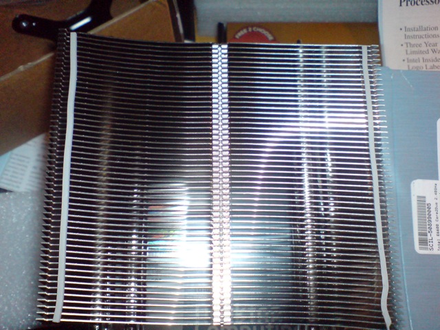
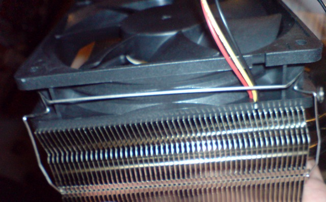
| Heatsink: | Thermalright Ultra-120 | ||
| Bits: | 12mm spiral wrap, 30cm 8pin ATX extension, 6 tacky back cable tie anchors, many cable ties, a very sharp knife | ||
IDE Optical using rounded PATA-133 cable. Power cables tied with red.
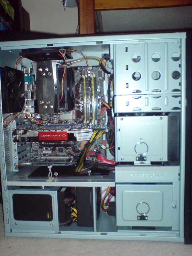
IDE-detailTo avoid too much cabling in the motherboard area, SATA power was threaded in behind the drive bay fan mount and SATA data was threaded in through a hole in the bottom 3.5" drive bay next to the motherboard. Drive bay cooling door is entirely closed, nothing passes through it. Cable tied excess power length underneath the PSU in the drive bay along with excess PCIE and the 4pin ATX. Be careful not to tie any cables where they obstruct your fans - I had the intake for the M-12 facing upwards, and tied the cables away from the smaller heat sensitive intake on the front.
SATA-detailFront panel audio, Firewire and USB all bundled up using the spiral wrap. X-Fi has an intel HD connector, P180B has an AC-97 panel, so you need to connect up the pins individually to get front headphone working without cutting out the sound card when nothings in it. Not hard, but be aware the block connector wont work.
fp-detailSpare lengths of FP connector, USB and Firewire spiral wrapped and tied here behind the now empty drive tray being used as a fan duct. Remember to remove the trays which otherwise block airflow.
intake-fanOne optical means lots of spare space - Spiral wrapped ATX extension and the opticals molex connector cable tied to an anchor here; the IDE cable is not tied to the power cables, but runs pretty close. C'est la vie.
power-detailSome of this is fiddly and frustrating, especially the fan and heatsink parts. Take your time, take a break when you need it, and google if you're not certain how to do something.
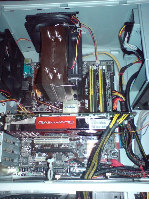
Hopefully, we end up with something like this. Terms defined here and here
Remove both drive trays, the lower bay fan mount and the front intake fan mount. Unscrew the ANTEC fans from the top exhaust and rear exhaust. Unscrew the fan from the lower bay fan mount. Remove the drive trays from the upper drive bay by holding the silver prongs in and pulling.
Suggested order: Softmount fans first, you want a lot of space. The top intake and exhaust are pains in the ass. The front intake and drive bay are easy - the fan brackets just slide out and clip in when you press/lift on their handly things. Do not insert drive bay or front intake fans yet, you'll want room to work.
For each fan, ensure the sticker side is facing the direction air should move; this means facing out of the case on the back and top exhausts, into the case on the front fan mounting plastic thingy, and towards the PSU in the bottom drive bay mounting thingy.
'Softmounting' the fans means using your strange stretchy rubber pointy things instead of screws to attach them to the case. Push one through each fan hole on the case until just the back circular stop is flat against the case side. Tuck the extended wobbly bit inside the case through each fan hole at the corner of the fan, then reach in, grip the nipple, and tug it till you hear or feel a slight pop indicating the angled 'arrow head' has come through the fan hole and is now holding it against the case side. When the things pop all the way into the case, or pulling one causes another one to pop out, sigh, remove them all, have a cup of tea, and start again. Softmounting will make your fans quieter, preventing vibrations resonating on the case metal. If you dont care about the noise, just use the screws - its easier.
Stick the black X shape thermalright heatsink block to the bottom of the motherboard, lining the threaded holes up with the CPU fan holes. Swap out the flexy silver metal plate at the back of the case with the holes for USB, audio, etc, with the one that came with your motherboard. Slide the motherboard in below the fans and nuzzle the connectors through the holes in the new silver plate. You will probably need to tuck fingers in above the USB and ethernet ports to hold the clips up and prevent them catching on the inside of the ports. Screw the motherboard to the risers already in the back of the case; no more are required.
Squeeze the PSU into its bracket and screw it into place. Fan intake (big fan) facing upwards, little fan facing into the case.Select the power cables to use; I had 2xPCIE, 1xSATA, 1xMolex (only 2 connectors on it), 1 8pin ATX, 1 24pin ATX. Attach 8pin extender, spiralwrap to protect it. The inside of the case is sharp. Attach all but the PCIE cables, but do not yet thread them through to the main motherboard area; thread the SATA power through the hole in the lower corner of the drive bay fan mount and tuck the excess under the PSU, along with the 4pin ATX. I had to snip a cable tie that was bundling all the ATX connectors together so that there was no tension with running the 8 + 24 pin to the main bay and the 4 pin out of the way.
Place cable ties through your 7 anchors and place them at strategic locations; its going to get cramped and you wont want to thread the ties later. I placed one to the far side of the power supply to grip the spares cable lengths and keep them under the PSU without blocking the fans, 2 alongside the motherboards right edge, just before the ATX24 pin connector and a little after it, one along the top edge where the 8pin extension will run, one inside the lower drive bay to prevent spare SATA power connectors brushing the fan, and one on the top of the drive bay roof in the motherboard side to the right of the sliding black plastic seals to tuck any excess ATX power into and prevent it fouling the SATA and Frontpanel connectors. DO NOT ZIP ANY CABLE TIES CLOSED YET. A single one of the open/close ties that comes with the case can be splatted in the middle of the space for the rear intake to hold cables while you build.
Carefully feed your SATA data cables into the drive bay through the rear hole in the top of the drive bay; this has sharp edges. You may want to wrap them in a little insulation tape if you're nervous, but they should be fine. Feed all the excess into the bay; you'll want it to allow the tray to be lifted in and out easily. Make sure you know which one you connected to a red connector (bootable drive) and which to a black connector (data drive).
Connect your front panel USB, and firewire blocks to their respective pins on the motherboard; these are the blue and red connectors near the bottom. Plug the front panel power, LED and reset connectors onto the ASUS quick-connect block, then tuck that onto the pins by the SATA connectors on the motherboard.
Attach the FP audio connectors to your sound card. Slot your sound card into the lower PCI slot, removing the blanking plate first, and screw it in.
Spiral wrap all the front panel cables up to the point they'll be tucked behind the front fan intake/drive bay. Pop the excess in the open/close tie that came with the case.
Screw rails to your optical drive with the silver prongs at the front such that their tips are flush with the front of the drive. Use a screwdriver to remove a front bay panel, then lever the metal plate behind it up and down till it pops off. Be careful not to let it drop onto your motherboard. Insert the CD into the hole till you hear the 'click' of it snapping in place.
Run your IDE cable from the red IDE connector to the drive; both cable and sockets should have notches that permit them to only be inserted in the right way.
Feed the ATX 24 and 8 pin cables and all your other power attachments (except the SATA we already fed into the drive bay) into the main motherboard area through the sliding door in the plastic seperator. Leave the thumbscrews loose for now. Plug the 24 pin ATX connector in, attach the 8 pin connector via its extension by running it around the right side of the motherboard and along the top to the small port in the far top left hand corner.
Connect the molex connector to the optical drive. Lay these cables as you want them to finish and draw any excess back into the PSU bay, tucking it out of the way under the PSU. Dont be tempted to use those cable ties yet.
Screw your drives into the lower drive bay tray, ensuring the fat side of the grommets faces upwards and the end of the drives with the power and data connectors faces the fan. Tuck the SATA data cables in the space under the drive in a loose curl and lower the drive tray in carefully, ensuring it doesnt snag any cables. Once in place gently tug any flex needed, attach the SATA power and data cables, and do the thumbscrew up, finger tight. Push any excess power cable back into the PSU bay; at this point you may do up the cable tie that stops the power in the drive section fouling the fan hole.
You should now have your drives in, connected to SATA and power, and screwed in, both optical and hard disk. Your motherboard should have front panel USB, firewire and audio connected and neatly tied in the intake hole. Your ATX power cables should be run alongside the IDE power and data, but not yet tied.
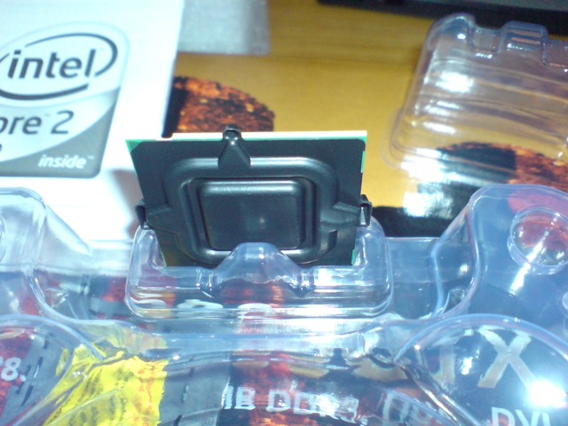
Lift the CPU closure on the motherboard and remove the protective plastic covering the pins there. Be careful to bend nothing. Remove your CPU from its packaging and remove the protective plastic over the CPU. Slot the CPU into the hole under the metal gate you just raised on the motherboard, such that it nestles lightly in place. It will only fit one way and has notches cut into it - no need to force it, just examine both socket and chip first and make sure you tuck it in right way up. Close the gate to secure it in place and tuck the lever back under its latch.
Slide the top part of the CPU mount through the heatpipes on the thermalright radiator, so it hangs loose and rattley, and stick the long thin strips of foam provided down either side of the radiator on the inside of the tabs sticking out at either side; this means they are flat, facing outwards to the case (not at each other), but in the slightly recessed portion rather than the thin extended edges at either side.
Tuck the fan mounting springs onto the top and bottom holes in the center of the radiator. They should extend out over the side you put the foam strips on. At some point they are almost certain to pop loose. When this happens, feel free to swear, but dont worry too much, they go in pretty easy once you have the knack of it. When this happens, just tuck em back in.
Put a small amount of thermalright heat goop on the CPU and use a business card to spread it into a thin, but consistent layer.
Repeat the process for goop on the CPU with the bottom of the heatsink; thin consistent layer.Place the heatsink on top of the CPU with the side that has the rubber strips facing your optical drive.
Using the spring loaded screws, tuck them through the holes in the loose rattley X mount you put through the thermalright heat pipes, and line them up with the black x mount attached to the bottom of the motherboard. LIGHTLY press down on it and screw until you feel it bite. Do not tighten it up yet. Do this for each corner; the sticky pad is not strong and if you overtighten one corner or press too hard you may push the lower X off, meaning you'll need to undo everything, remove the motherboard and stick it back on, before starting again.
Tighten the screws until they wont turn any more; at this point STOP. They do not need to be super tight.
Tuck one of your S-Flex's onto the front of the radiator, sticker facing into it, and hook the pointy edges of those annoying poppy out clips into the fan holes at each corner. It should hold the fan fairly securely.
Attach the fan 3 pin connector to the Top Right 3 pin header on the motherboard labelled CPU. Attach the exhaust fans to the headers nearest them. Cable tie the loose connector wire through the holes in the fans, case grille, or whatever you feel like to ensure they dont get tabled on fan blades or cards being removed and added.
Nearly done. Go around checking your cables lie where you want them; the idea is to keep them flat against the case, ensure they dont 'bulk up' in a way that might block airflow from any of the fans in the case, and that they dont hug anything with a heatsink. When they're running in a way you're happy with, pull the ties closed and cut the excess off. Leave a little slack so you can get a blade under the ties to cut them free when you come to change whats in your case in the future. Do not yet tie the one in the PSU chamber with the loose power flex.
Insert your graphics card. Remove the blanking plates from the case first, then screw the card into their place; make sure you hear the click from the blue clip holding the card in place.
Attach the PCIE cables to the PSU and run them into the top case, then onto your card. Pull flex back into the PSU section and tuck away with all the rest under the PSU. You may now tie the final cable tie holding the loose flex under the PSU and away from the fan. You may also wish to cable tie the various modular cables and ATX cables on the near side of the PSU to one another to prevent them obstructing the smaller intake fan as they run up through the divider.
Slot the Drive section fan into place and feed its 3 pin fan connector up to the motherboard section, plugging it into one of the connectors by your spiral wrapped front panel cables.
Slide the divider doors closed and do the thumbscrews up, nudging the power cables into the cut out such that there is no space along the flat gaps of the dividers.
Slot the front intake fan into place and feed its 3 pin connector over to the motherboard IDE connector, where you'll find another 3 pin fan header. Plug it in and add it to the bundle on the reusable antec cable tidy.
Put any spare screws, etc, into the toolbox on the back of the now empty middle drive bay, slot it into place hiding your spare cable flex and providing a funnel for the front fan, and screw it back in with a finger tight thumbscrew.
Plug your RAM in. If you only have two sticks, pop them in similarly coloured slots. Do this by pushing the white clips at either side open, popping the ram in and gently pushing. The clips should snap closed on their own. If you find they dont, try turning the ram around. Once again, it will only go in one way but its not entirely obvious by mk-1 eyeball which way it is. Dont force it.
Plug in a monitor, keyboard, mouse, turn on, pray.
If it worked, dont forget to tweak your BIOS settings...